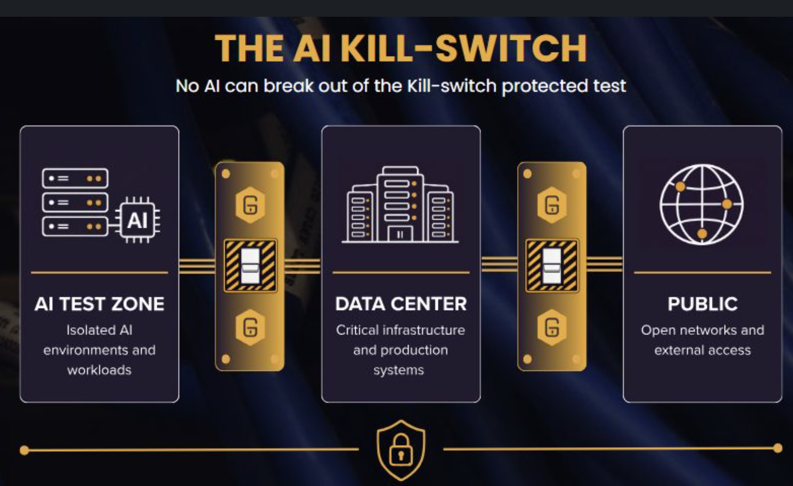
Physically contain AI before it reaches critical infrastructure

Put a physical limit on AI Movement

Scroll to Explore

The AI Problem

AI changes where risk can travel.

High-density AI clusters create unpredictable east-westtraffic and new pathways into shared infrastructure.

Software controls remain vulnerable to misconfiguration,policy failure and software bypass.

Security leaders increasingly need a concrete answer: whatphysically stops AI from reaching critical systems?

the principle

FireBreak is not simply a kill switch. It is a physical network control point that can be configured and deployed as one.

Physical control, placed directly in the optical path.

Core story

The FireBreak Story: A–B–C

AI moves fast. Threats move faster. FireBreak stops them at the connection point.
A
AI Workloads
High-density AI clusters generate unpredictable, high-volume traffic and create new attack paths into critical systems.
B
Breach Path
The optical connection between AI infrastructure and critical systems can become a high-speed route for unauthorised access, lateral movement, or data exfiltration.
C
Containment
FireBreak is the physical AI kill switch. When the risk escalates, it breaks the connection—isolating the AI environment from everything it can reach.

Physical Control Layer

What Is FireBreak?

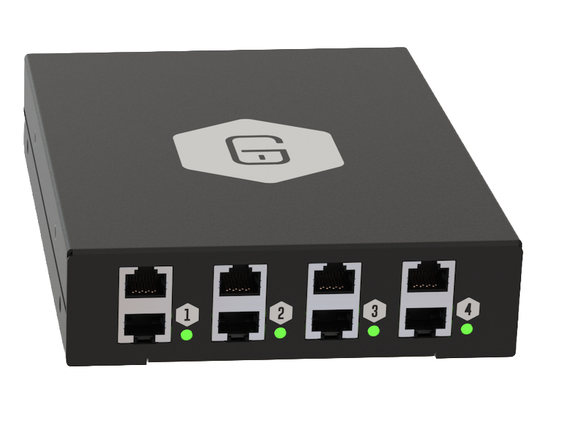
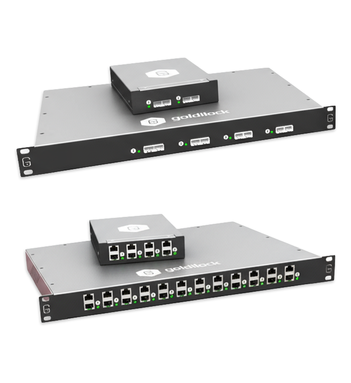
FireBreak is a physical control point in your fiber backbonethat decides which AI traffic paths are allowed, shaped ordenied. It is a hardware kill switch for AI connectivity, not justanother software rule.

Placed between AI clusters and core networks

Controls direction, speed and reach of AI traffic

Works alongside existing firewalls and segmentation

New case, venting, power supplies, 4x fans, deeper case
New heat sinks and QSFP subassemblies
New PCB layout and I2C based switch controllers
New thermal monitoring and smart fan control options

CAMPAIGN HUB

Explore the AI Kill Switch Story

A modular overview for security, network and infrastructure teams evaluating physical controls for AI connectivity.
Goldilock Partners with Frame Communications to Secure Ireland
June 10, 2026
Software-based defenses are struggling to keep up with the speed of modern, AI-driven cyberattacks. To bring a powerful new layer of defense to the region, Goldilock Secure has partnered with Frame Communications to distribute our FireBreak™ solution across Ireland. Effective May 1st, 2026, this partnership enables Irish enterprise, telecom, and critical infrastructure organizations to utilize hardware-enforced network disconnection against sophisticated threats.Why Frame Communications? With over 25 years of experience in the telecommunications and enterprise markets, Frame is a trusted name across the UK and Ireland. Frame will leverage its extensive network of resellers and managed service providers (MSPs) to accelerate the regional adoption of FireBreak™. "Frame is a strong addition to our growing global partner network, which has expanded by more than 40 channel partners in just the past six months," said Steven Brodie at Goldilock Secure. "Their established presence will play a key role in accelerating adoption." True Physical Layer-1 IsolationRelying solely on software to stop a breach is a gamble. FireBreak™ allows organizations to instantly sever connectivity at Layer-1 using non-IP, out-of-band commands. This cleanly isolates compromised network segments without taking an entire network offline."Our customers are looking for practical ways to reduce cyber risk, as well as the ability to isolate and contain threats without impacting operations," added Gavin McGowan, Managing Director at Frame Communications. "FireBreak is a perfect fit." To ensure seamless deployment, Goldilock and Frame are delivering comprehensive, end-to-end support — from solution design to local sales and logistics — for Irish resellers and telecom providers.
Read More
View all blog posts

Real deployment model

THE campaign leads directly into the blueprint

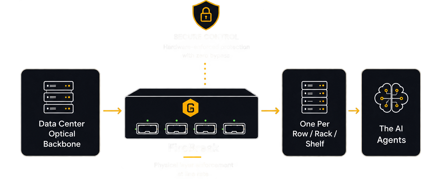
Move from the simple A-B-C story into a practical rack-to-rack deployment model, showing exactly where FireBreak sits between AI infrastructure and the optical backbone.
DEPLOYMENT SCENARIOS

Where FireBreak Fits Today

Physical segmentation for environments where AI access must be demonstrably controlled.

AI & DATA CENTERS
One FireBreak for EVERY Firewall.
Physical. Deterministic. Uncompromising.

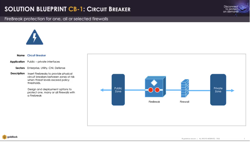
Circuit Breaker

Circuit Breaker
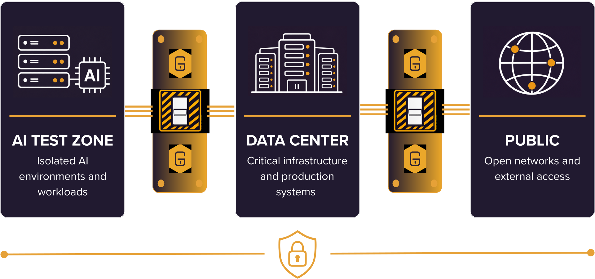
Place FireBreak alongside existing firewalls to create a physical circuit breaker between network zones.
View Full Blueprint

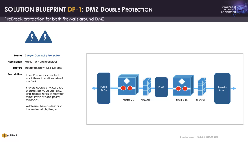
DMZ Double Protection

DMZ Double Protection
Deploy FireBreak units on both sides of the DMZ to provide physical protection between public and private environments.
View Full Blueprint

3 Security Airlock

3 Security Airlock
Create a physical airlock between public, intermediate and private zones, allowing only the required connection at any one time.
View Full Blueprint

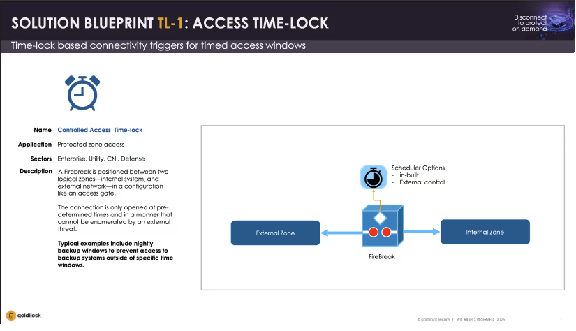
Access time-lock

Access time-lock
Schedule when connectivity is enabled or disabled for maintenance, backups and time-sensitive access.
View Full Blueprint

Physical Control Layer

One FireBreak. Multiple Ways to Protect Critical Infrastructure

FireBreak™ adds hardware-enforced separation alongside existing network security.
Four deployment models providen controlled, physical boundaries between public, private and critical environments.

Line Rate
100G - 800G
Zero Trust
No bypass
Physical Separation
Hard isolation at the physical layer
Deep Segmentation
Control traffic between any zones

Specs Snapshot + Datasheets

Key Specifications

A concise technical overview with direct access to product documentation.

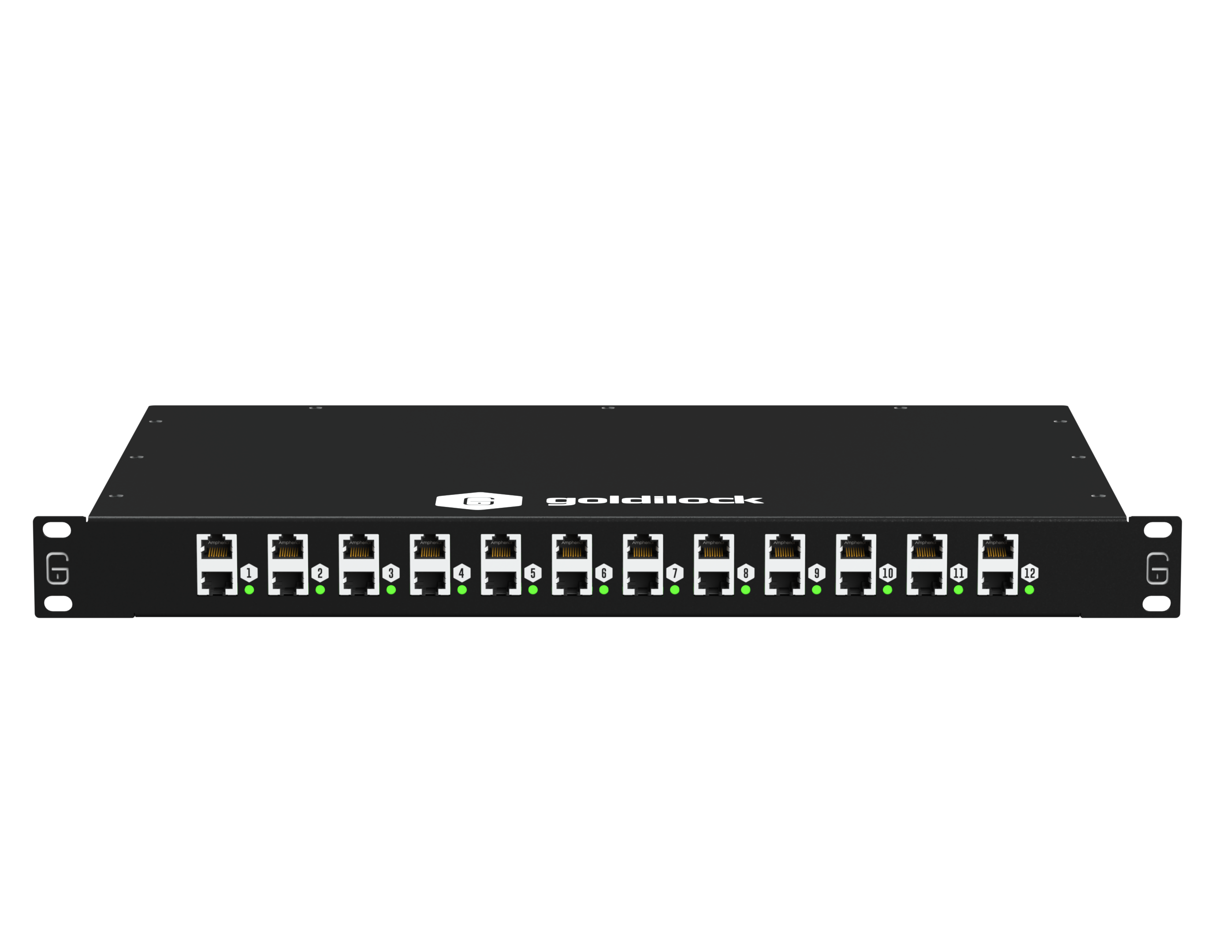
Tech Specs | 12 Port Ethernet RJ45 Variant

Form Factor
1U Rackmount (19")
Interface
12 x RJ45 port pairs at OSI Layer 1
Throughput
Up to 10Gbps per port pair
Management
Out-of-Band Management Interface via Web Browser (Built-in)
Remote Trigger
Via SMS with number filtering, 2FA/OTP authentication, granular port access
Interfaces
1 x SIM slot, 2 x SMA Antenna connectors
Power
110V to 240V AC @50/60Hz, ~11W average consumption
Operating Temp.
0°C to +60°C
Compliance
CE, UKCA, CISPR 22/32, FCC Part 15B Class A

datasheets

Protecting Your Network with On-Demand Physical Disconnection

Protecting Your Network with On-Demand Physical Disconnection

Version: 1.0

Date: Aug 25, 2025

1P-01
Networking
Download
How to Regain Control of Critical Systems in a Cyber Crisis

How to Regain Control of Critical Systems in a Cyber Crisis

Version: 1.0

Date: Aug 12, 2025

1P-02
Response
Download
Automated Cyber Defense for Government and Critical Infrastructure

Automated Cyber Defense for Government and Critical Infrastructure

Version: 1.0

Date: Aug 25, 2025

1P-03
CNI
Download
Executive-Level Control for Disconnecting Threatened Systems Instantly

Executive-Level Control for Disconnecting Threatened Systems Instantly

Version: 1.0

Date: Aug 14, 2025

1P-04
Override
Download

FAQ

Can port connections be scheduled automatically?

Yes. Time-based port scheduling is a supported operational mode and is useful for DevOps segregation, timed third-party access windows, or out-of-hours isolation of non-critical systems.

Do ports time out after inactivity?

No. By design. Disconnection and reconnection require explicit authorized commands. This prevents accidental reconnection but also means operational procedures must be defined for returning to a connected state after an isolation event.

How do organizations typically decide when to disconnect?

Two primary operational models exist:

  1. Normally connected — the FireBreak™ sits inline and is triggered to disconnect in response to a threat, alert, schedule, or procedural event
  2. Normally disconnected — assets are isolated by default and only connected when service is actively required, such as during scheduled maintenance windows or authorized third-party access

Many deployments use a combination of both models across different segments.

‍

Will installing a FireBreak™ risk accidental downtime?

This is a common concern and, in practice, a manageable one. FireBreak™ is designed to be operated by the same staff who already control critical systems — network, security, and processing teams. Standard operating procedures define when and how ports are opened or closed. Accidental disconnection carries a similar risk profile to accidentally removing a patch cable, which trained operations staff already manage routinely.

‍

How do administrators access the management GUI?

Via the rear Management Console Port. Connect it to a dedicated management network and access the device’s IP address through a browser. Security aligns with NIST 800-63 requirements, including two-factor authentication, brute-force protection, and full audit logging.

How is out-of-band access secured?

The SMS interface rejects all messages by default. To authorize a user:

  1. Whitelist their mobile number
  2. Assign specific port permissions
  3. Generate a unique OTP seed key compatible with Google Authenticator, Microsoft Authenticator, or Cisco Duo

Every command must include a valid OTP. Failure to meet any of the three criteria results in rejection.

What commands are available?

Enable port [1–12], Disable port [1–12], and Status port [1–12]. All commands require challenge/response authentication and are case-sensitive. The full command set is documented in the Administration Guide.

How are users and administrators defined?

There are two roles. Administrators configure the appliance, provision users, set port permissions, and manage OTP seed keys — exclusively via the rear Management Port (ensuring physical separation of duties). Users are authorized to send connect/disconnect commands to assigned ports via the secure messaging stack. Users have no access to the Management Port.

If you're still in search of answers, we encourage you to explore our informative FAQ section.